New version!
 So far:
- Built-in FFT engine, works with soundcard directly, via WASAPI. No need to use external FFT program.
- Huge FFTs (up to 8,388,608 points!).
- "Sliding FFT window" - ability to make FFTs faster than time required to refill the buffer. Took the idea from TCP/IP transmission speed control called "sliding window" . Sweet!
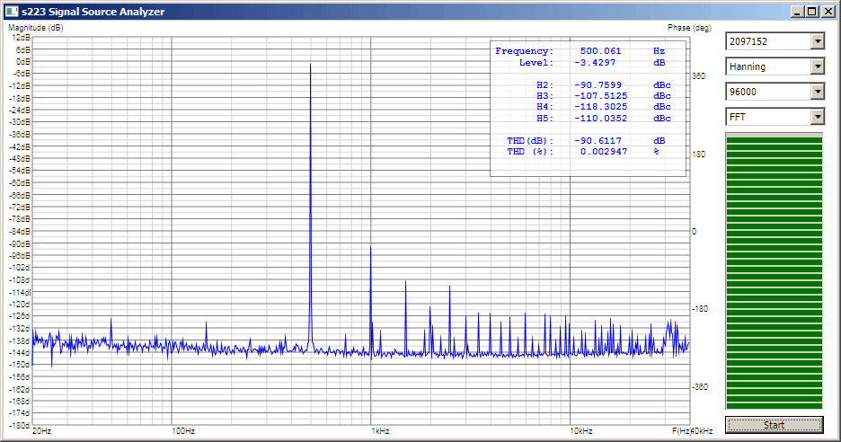
- Regular FFT analyzer plot with THD(%), THD(dB), H2-H5(dBc) measurements.
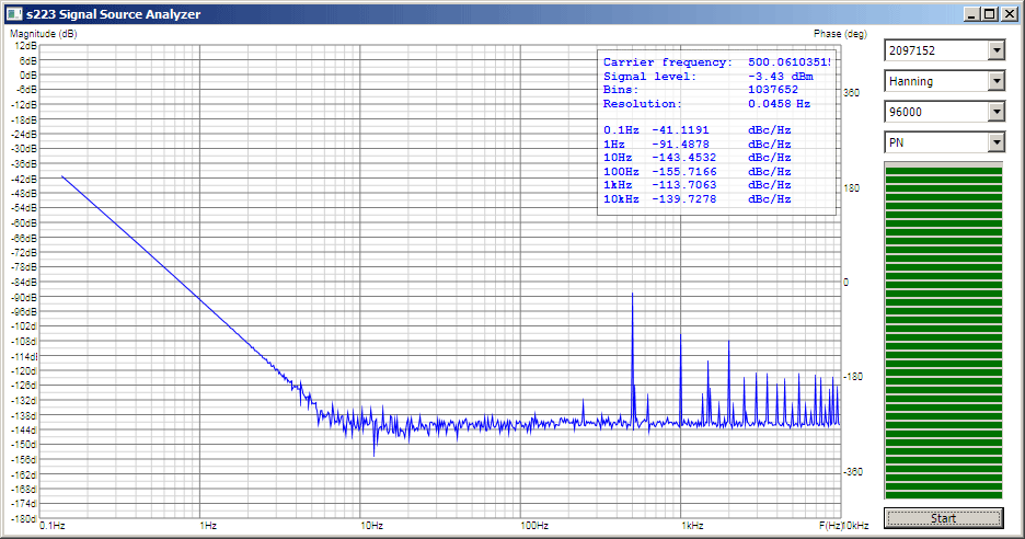
- Phase noise measurements mode, at offsets 0.1, 1.0, 10, 100, 1k, 10kHz.
- Buffer fill progressbar. Extremely important thing if you need to wait 3 minutes for the buffer to fill.
TODO:
- Gradual FFT window change as the buffer fills-up. Say we want 32k FFT - as the buffer passes 1k, 2k, 4k, 8k, 16k points - we can do 1k, 2k, 4k......16k FFT before we reach the final 32k point in the buffer and are able to FFT it. Sweet, as you see the FFT before you get the final FFT - so you could see if you've made a mistake/got some noise in the setup without a need to wait 3 minutes for the final FFT...
- Settings storage/presets recall.
- Command line execution (?).
- Semi automated test sequences (push "measure", get result).
- Attach to measurements database, with export of measured data, plots, management of serial numbers of measured equipment, data on cross-correlated xtals used in the setup e.t.c.
- Fix the "memory overuse" problem. It sometimes hits over 800Mb in memory use and then crashes :) Yep, a bit of cleanups and semi-sequential code should help.
A little piece of software, that eats the results of some FFT RTA program (lots of bins, cca 18MB file), finds out the center frequency, and then cleans them up, displays them and a bit "measures" them, in a jitter-redisue-like look.
Just some preparations before i start to build my own clocks, low phase noise ones.
The plan is as follows:
- Take a reference clock
- Mix the reference with measured clock
- Since

Where "a" and "b" are our reference and measured clocks, on the output of RF mixer (x operation) we get two sidebands, the "cos (A - B)" and "cos (A + B)", of frequencies "A - B" and "A + B" respectively. If our A and B will be close enought in the frequencies, we'll get quite low-frequency of "A - B", which could be directly measured with a regular soundcard, given we filter-out the not required "A+B" stuff. The "A-B" will represent the frequency deviation of measured clock from the reference.
- FFT that "A-B", get the sidebands, throw 'em thru the s223 Signal Source Analyzer and within 1-click you get that cool plot, with measured markers at 0.1, 1, 10, 100, 1k and 10k Hz offsets.
Sweet?
2 days later.... The Real Thing:
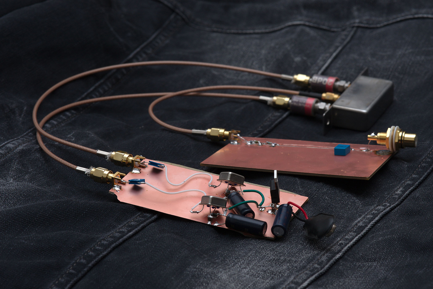
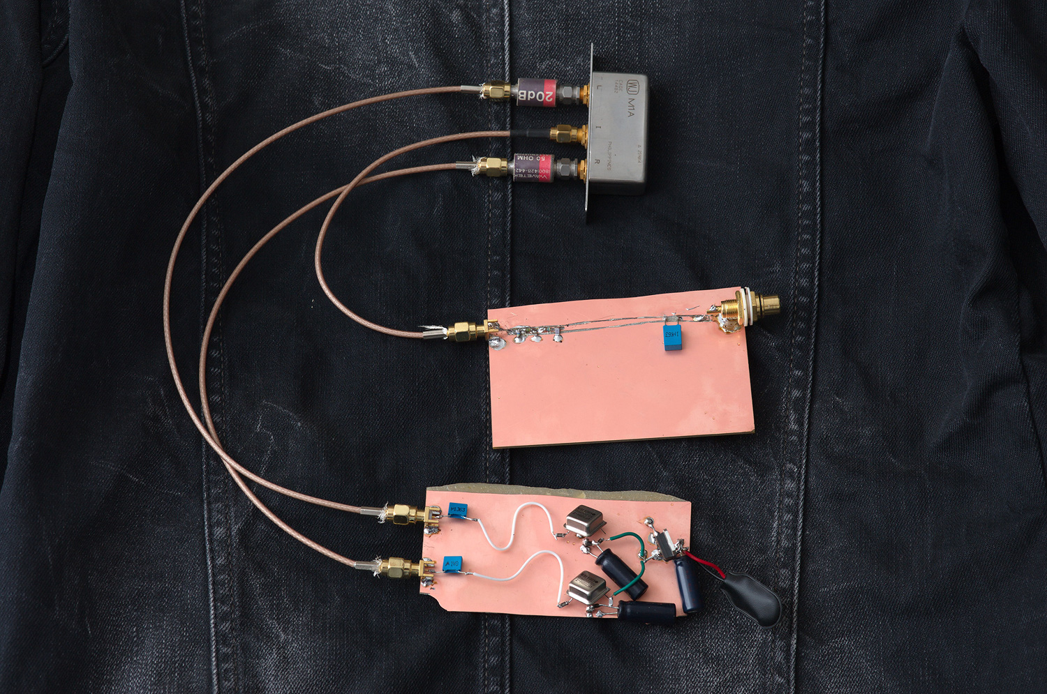
Two 50MHz oscillators, 20dB attenuators, 0-2GHz mixer, passive LP filter, M-Audio Audiophile FireWire soundacrd. Need the LNA, desperately.
The rig:
And one of the measurements:
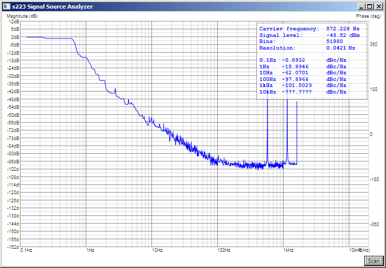
Poor performance, noise floor is too close, carrier is -48dB. I need LNA!
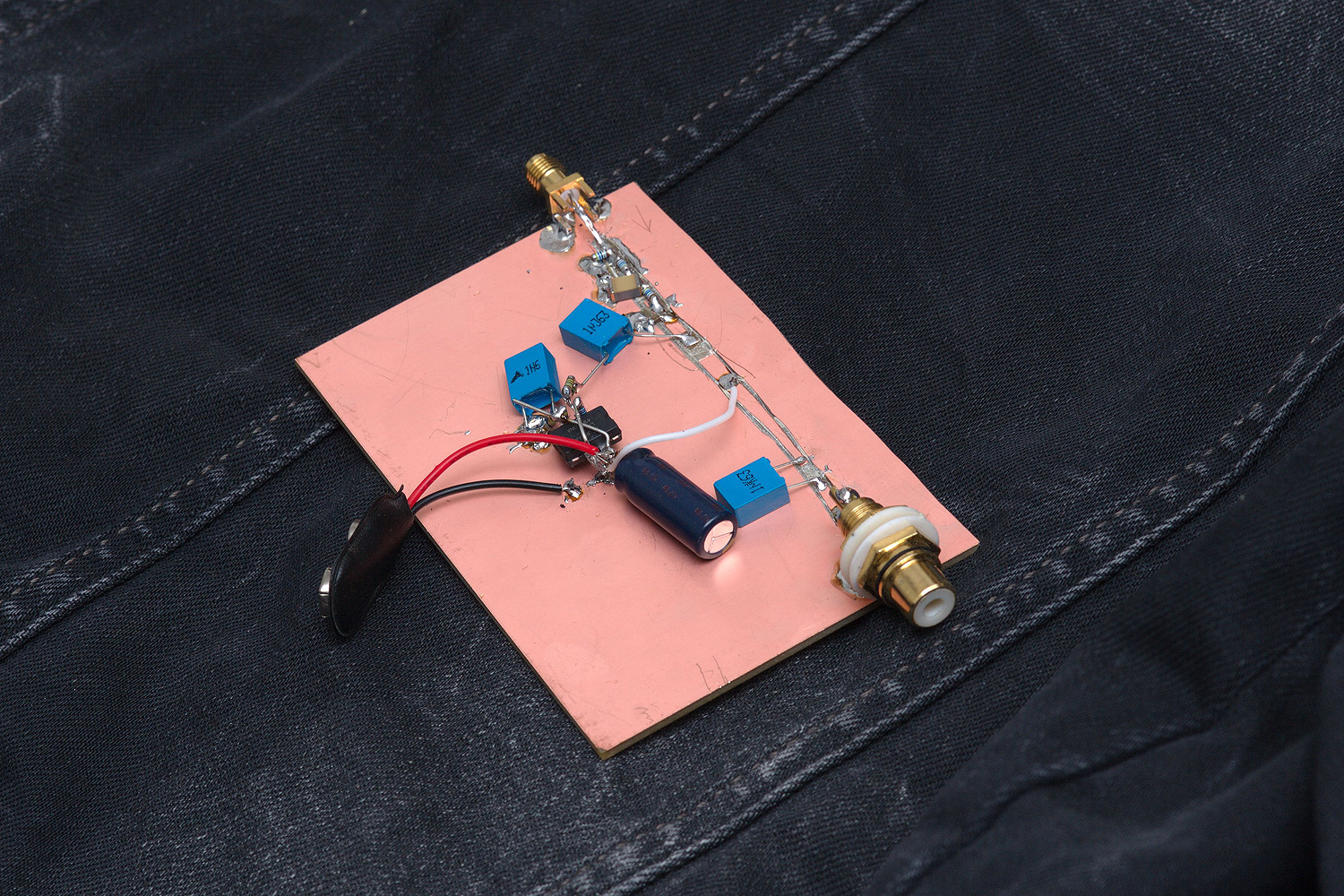
Few hours later and with LNA:
The LNA is based on inverting LME49710, with circa 26dB of gain.
Had to change 22uF X7R cap on virtual ground divider as it was too damn microphonic. 1uF MKS did the trick.
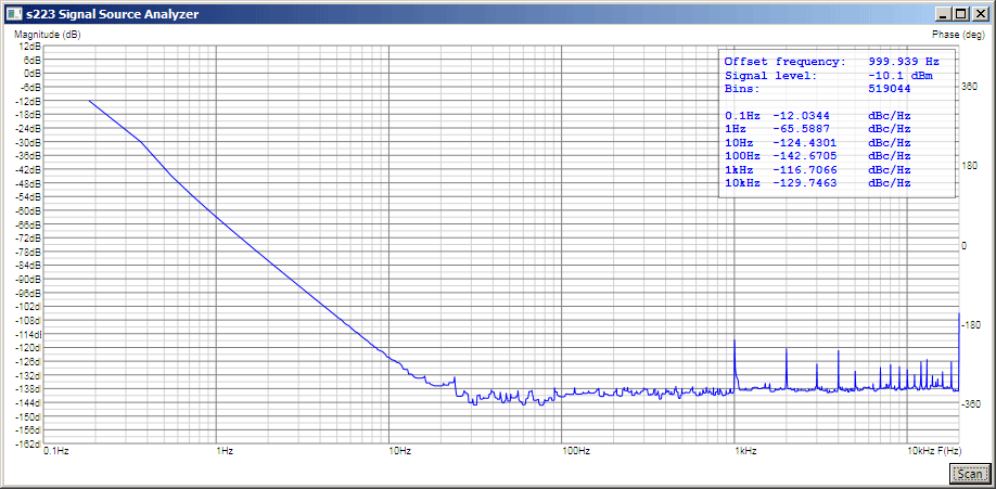
And the result of LNA use: (this pic is with 20dB LNA. I've updated the LNA with extra 6dB):
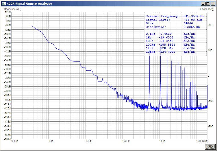
The clock being measured:
http://www.datasheets360.com/pdf/-8111351097260227119
Quoted for sub-1ps >1kHz in the datasheet.
My measurements say 3.7ps >10Hz, 0.4ps >100Hz. Then i hit the noise floor. Hm... Time to check what's going on with PCM4222EVM, i've seen 160-170dB noise floor there, versus the 140-150dB of M-Audio....
Yet, kinda irrelevant, as we need the close to the carrier phase noise, not >1kHz.