This project is quite remarkable as it does what every well-seasoned electronics engineer does – it guesses. It learns by guessing, and finds the most optimal (yet cheap) way of delivering required performance from any given circuit. A million times per second.
So, what is it?
- You set the target response of the circuit (by drawing real-world biquad filters on the chart)
- You draw approximate circuit that might implement the desired target response (without component values, as they are nearly impossible to find out without guesswork)
- … yada yada …
- You get the component values that implement desired target response! Magic!
What it does:
- Simulates any given electronic circuit (passive, analog), connected to any supplied impedance (important)
- Randomizes component values in the circuit, and learns the outcome of every randomization (some might call it Monte-Carlo). If you keep all of the solutions in a neat array along with component values we’ve got thru randomization you’d get…
- Machine Learning! All you have to do is calculate the distance (evaluate similarity) between given target response and previously obtained circuit solutions and pick the best one. Ta-dams, Artificial Intelligence! Almost there!
- The moment you get a good match from previous step, you could kind of improve it by slightly randomizing the values of components (like 10-20%?), and find a lil bit better solution thru several passes of randomization and pinpointing (10, 8, 5, 1% “fuzziness” for each cycle).
- But the most important thing is… Magic!
Get
XS01 Xover Studio now! :)
Update 14:
Hella semi autoMATIC filter application! You choose the next shape, the program chooses how to fit that shape into filtration chain to get closer to target :)
 Update 13:
- Reverse-engineering of biquad filters, you get original function parameters (function type, order, F, dB, Q). Quite fast (20 biquads/s, 0.01% parameter precision).
- Trying to integrate auto-tune feature to DSP: for now it draws a shape of filter which you need to implement to get from current response to target. Sweet :)
 Update 12:
New design targets! DSP Editor, where you can design filter chains with biquads! Update to UI - much more friendly, much more sexey!
 Update 11:
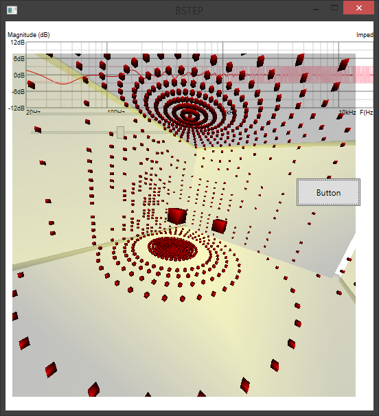
Attempt was made. Environment modelling in all of it's glory and hatred.
What worked:
- Baffle step (per Vanderkooy's first whitepaper which i haven't yet acquired, but my simulations fall within less than 0.1dB to other _elaborated_ simulation software, so i've got it right.). Mine has impulse response too, which is kinda NICE as you could not only see how the baffle affects driver response in the frequency domain, but also see that there is no actual +6dB rise signal-wise in overall manner but a reflection of original speaker's response off of edges. It's not "_10_____", it's "_5__3_2_". So our ears *could try* to ignore that reflection, if it far enought from driver itself (late reflections, hearing ignores them).
What haven't yet worked: (i mean, it works, but there is some lack of correlation between measurements of ugly busy warehouse-type room versus idialized rectangular sphere in the program)
- Room modelling based on Image Source Method. That's when you take your source (speaker) and mirror it against the walls to create images of the source. Then you mirror these images over and over again.
- Room modelling based on Diffuce Ray Tracing Method, where you stochasticly shoot rays from the source into 4Pi and every hit on the wall generates a wave to the "listener" (simulatess the part where sound wave diffracts rather than reflects from the wall). Unlimited depth just like in ISM above.
All of these have implemented both frequency domain and impulse domain responses, as well as wave decay over distance and each wall's reflectivity and diffusiveness rations. Room's decay simulation works and actually matches of what has been measured!
- All of this required me to develop a computational class for "Impulse" response which got most of the typical math functions (add/substract, scale, convolution) as well as (important!) deconvolution/inversion (based on Least Squares QR factorization method, a linear algebra solver in Math.Net, thank you! :) )! So, now i can generate inverse-impulse responses to measurements to create total room and speaker correction FIR filters (DIRAC here i come).
A pic of debugging session: (yep, not my best 3D render, at least it's live and programmatically generated). As can be seen, buggy ray hit test won't give satisfying patterns on the walls. Fixed it!
 Update 10:
Hooray, everything works!
New: Frequency response merge tool, now you could get these clean low-frequency responses too!
 Update 9:
Another BIG update. Now with UI that makes sense, as well as event engine that makes everything update in real time. MVVM, bindings and ooooh. You change input response? Everything that uses it recalculates and displays results. You change targets? No worries!
 Update 8:
THIS ONE IS BIG.
Really big. I've started to put all the previous parts together so i could
- draw the circuit
- define target response
- click the button and see the magic
well, magic happenned and it took like 30sec to solve the more-or-less complicated circuit i've defined, as i needed to ramp-up the resolution for these shallow notches. Uh-oh, FAILURE.
Yet,to get that solution i had to go thru pretty much every possible solution of that circuit... Uhm... what if i store all the solutions and their charts in memory, and then do a simple look-up of "most appropriate solution" to the target response from the memory? (calculating distance between 2 charts is very efficient and simple)...
Hella yes! Let's do it in real time, as it is exceptionally fast!
BOOM, MAGIC: it calculates the circuit by real-time-changing target response in real time:
 Update 7:
Now we're getting graphic. Or graphical or something... I desperately need a target response which is monotonously sloped from top to bottom. No possible biquads could cover this range of frequencies in such a smooth linear manner (linear on log/log scale, thus very loggish)... Untill we chain a bunch of biquads together (shelving filters)...
SUCCESS:
 Update 6:
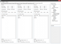
Now we need a tool to draw target responses. With a mathematically possible curves, typically your's truly low-pass, high-pass approximizations as well as PEQs, shelves and everything.
Should conform to LTI, as we are talking passive-analog schemes to be solved.
So, IIR filters we go, and biquads we use!
Lil bit of chaining of biquads, tying their parameters to the movable "control points" on the chart and fast recalculations of signal chains in the background as you move the mouse and we are set:
 Update 5:
Live dragging of component values on the schematics and LIVE simulation of the resulting circuit!
 Update 4:
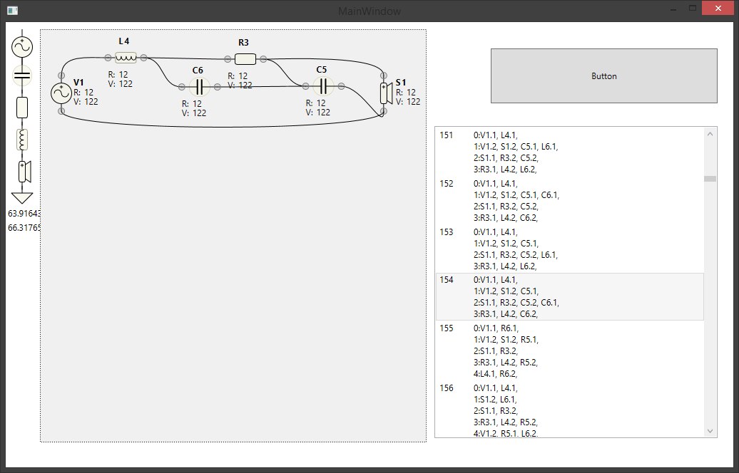
Circuit mutations! Creates all possible interconnections and components for specific number of parts.
Like if we decide on 3 parts, it produces all possible interconnections and configuration of component types.
Might help us in the future for absolutely-everything-solver implementation...
 Update 3:
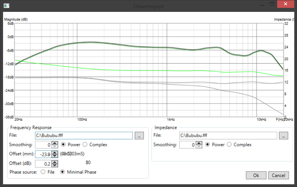
Import of frequency response and impedance files.
- With smoothing! (mathematically approximate, yet more-or-less similar to other software packages. Frequency-dependant window function of the filter on log scale, so it keeps it's vital property of being "n-octave", in 2 modes - classic and complex!).
- Phase extraction from frequency response via Hilbert Transform.
- Various tweaks as time/phase alignment
 Update 2:
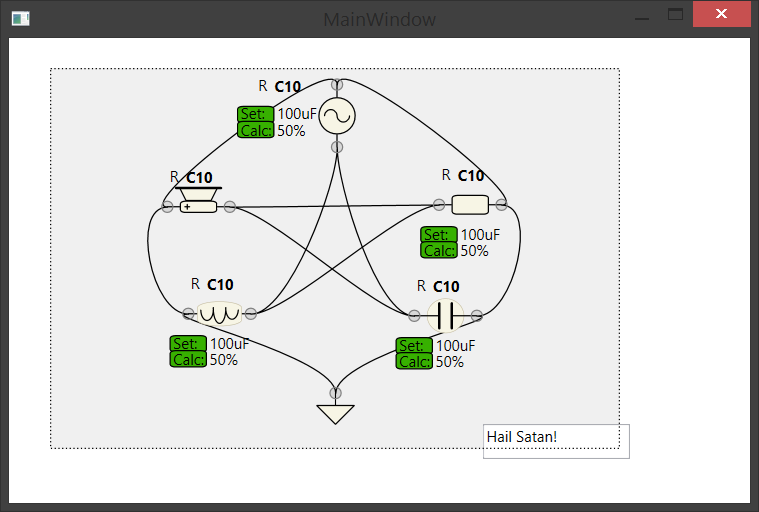
Now we need some UI for circuit editor. Like this fancy one. Yeah, CURVES! (and easier to code, damn those splines):
 Update 1:
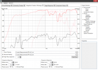
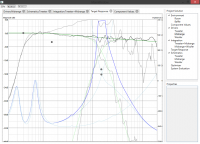
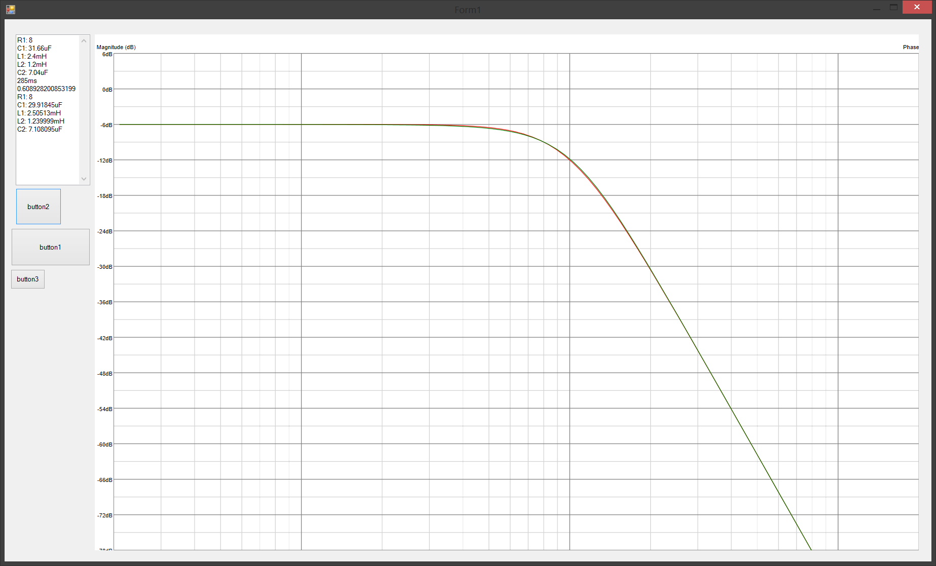
Comparision of target response Vs solution. Green is target, red is solution. They-are-perfectly-the-same.
IT WORKS!
 Hooray it's alive and kicking!
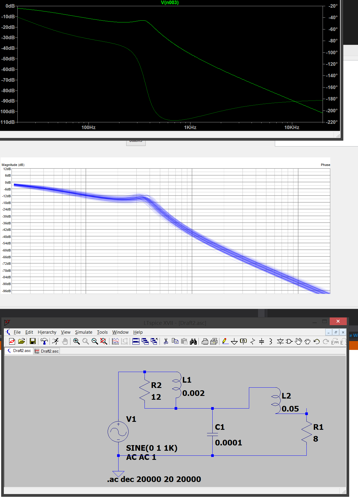
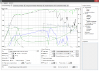
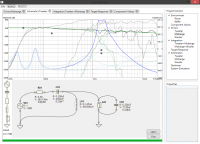
Top pic - simulation by LTSpice
Mid pic - my solver iterates thru randomntess (depicted by several layers of blue lines) to get the solution!
Bottom pic - circuit i am trying to calculate (it's simulation is in the top picture).
Monte-Carlo solver looks kinda promising!
AND MY SIMULATOR IS ACCURATE!!!