 >> Schematics <<
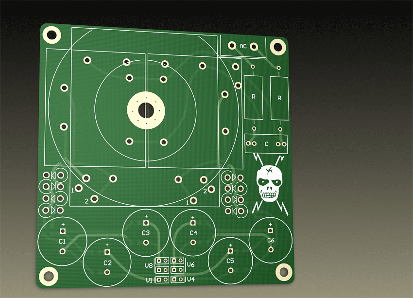
What do we have here?
- Input AC filtering with resistors in each 220v wire and a 0.1uF cap in paralel to trafo. This cap assures there won't be any HF noise on the trafo winding, and resistors reduce a bit the 220v line voltage to reduce the induction too.
- Resistors before and after the diode bridge increase conduction angle, decrease sharp peak currents and prevent diode "ringing".
- Smooth rectification goes futher with schottky diodes, which are soft recovery and don't exibit much the usual "tzang" ringing.
- After the diode bridge we have a CRC filter which performs better than regular CC filter.
- There is two CRC filters with one C in common. It gives two clean detatched from each other outputs per transformer winding.
- Transformer's windings and their PSU circuitry are separated - you can use it as you like - to provide two +5v outputs - for digital and clock, or make it "bipolar" +/-15v for analog stages.
- Toroidal, 2-brick and one brick transformers are supported, but the "brick" types don't have a standard for their footprints - i made the board for the trafos i had in the drawer... You'd better stick to toroids. The circle on the board is 75mm in diameter (circa 3").