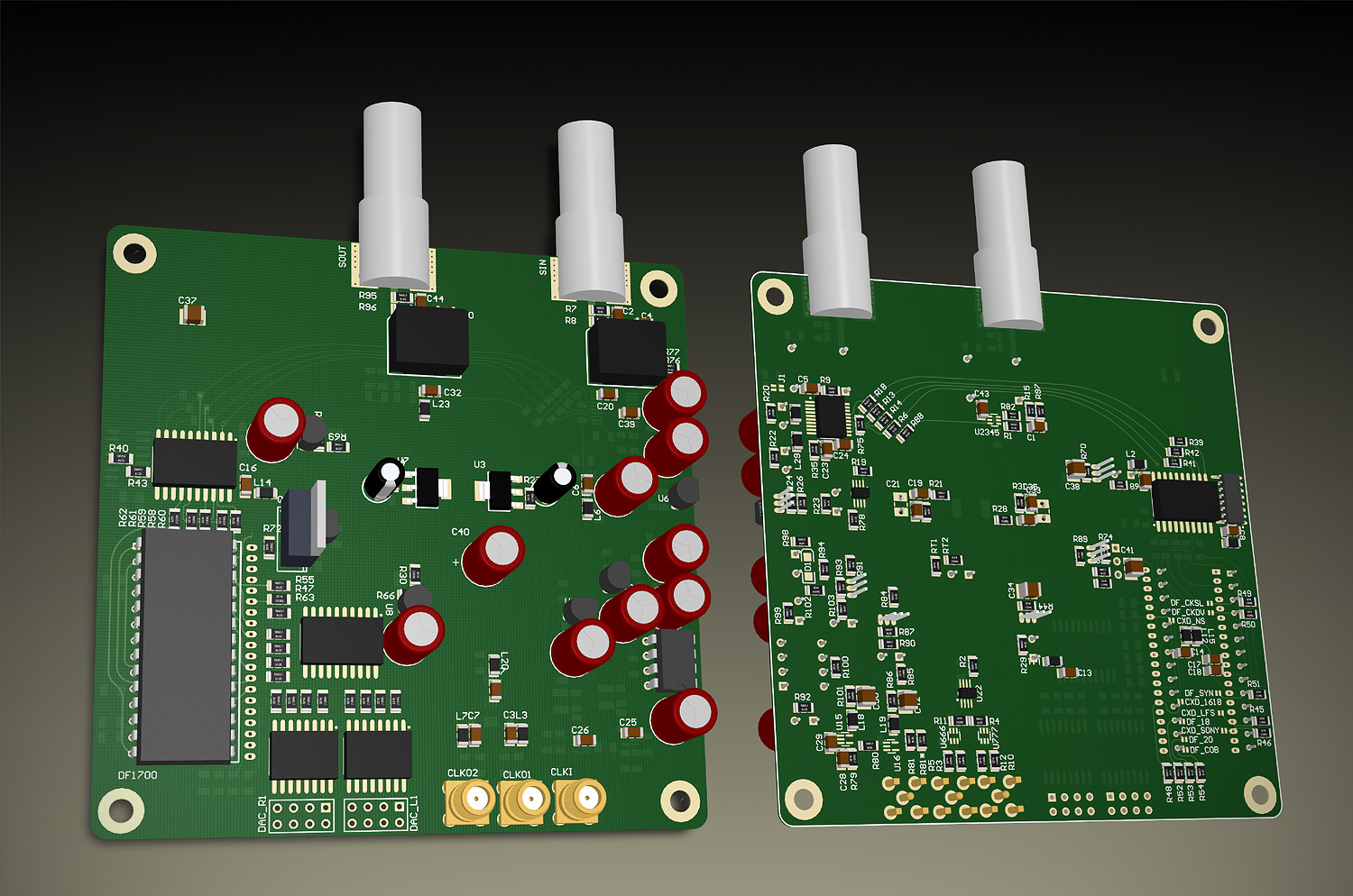
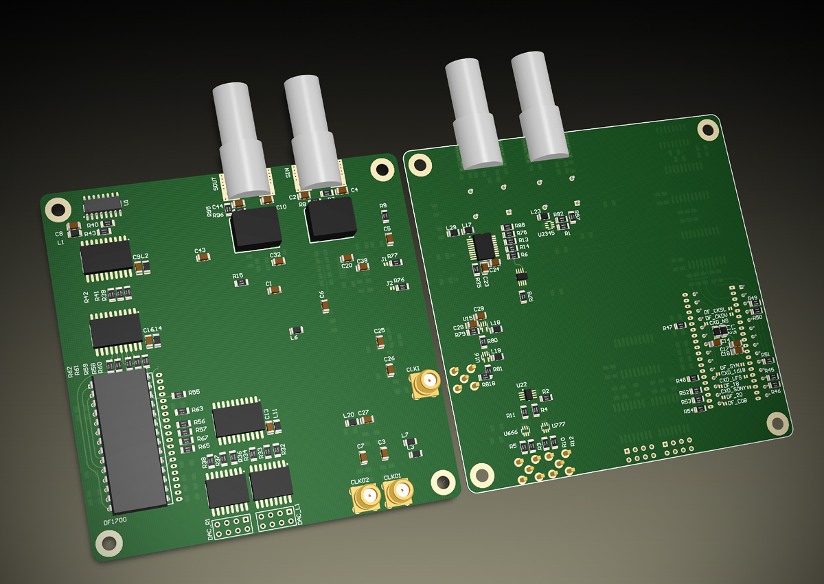
DigiCD MK-II, v0.1: Schematics.
- Power supply section added. Everything goes thru shunt regulators, as i don't want the data/audio-correlated noise to go all over the place into transformers etc.
- Some pin swappings for better layout.
- 106 resistors on the PCB. Heck, i'll add another 10 for PS input section.
- Ground planes to come, with cutouts etc.
- Power/thermal things should be calculated to check whether design is viable.
- Shielding cage for oscillator.
- "debug" resistors for WM8804 - on 12MHz and MCLK outputs - to measure their phase noise performance.
So far, layout is 85% complete.
- Oscillator power supply should be simulated, as it is a kind of "mock-up". Op-Amp as a buffer for heavily-filtered LED reference, fed from Op-Amp output. Shunt regulator for OpAmp to make sure the currents won't flow all over the PCB. Noise will mostly be OpAmp's, so a good low noise opamp, with enough power output, rail-to-rail (or at least 5v compatible), and good PSRR should be used.
Simplified board, no CPLD, 44.1k-only support for back syncing. Thus "CD" in the name.
DigiCD MK-II, v0:
Schematics v0
 Now with schematics
! Whew, that was rather crazy /done it in 1-1.5 days/.
Some bits are missing as well as PS section which would be as monstrous as the other circuit...
PCB layout would be... meh... interesting. in two layers.
V2: (pdf)
This board is based on backsync SPDIF interface i've verified -
here.
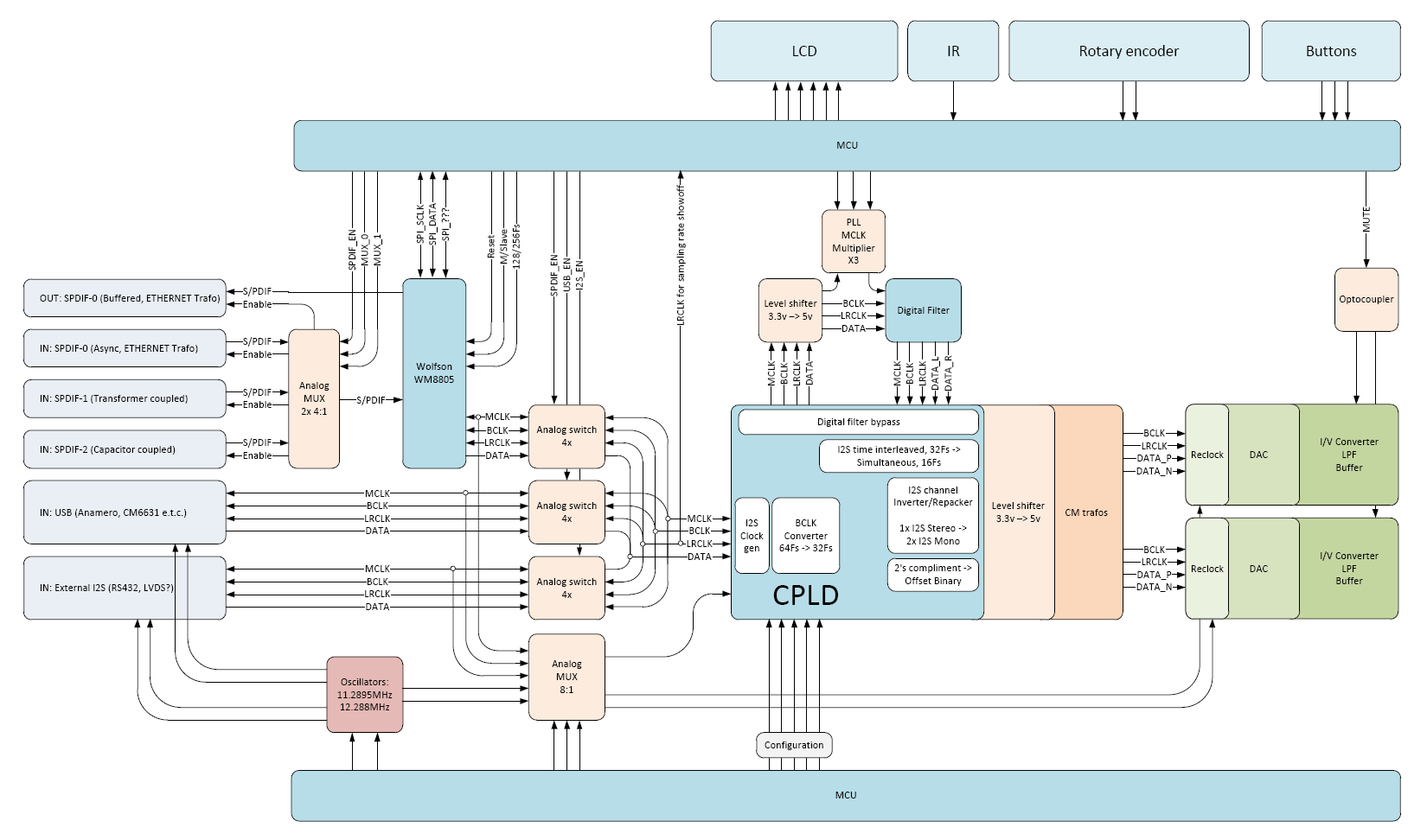
This board fills the gap between any SPDIF source and DAC boards.
The block diagram looks like this:
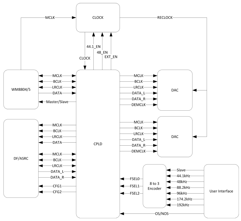
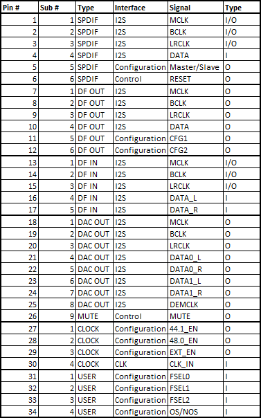
CPLD pin allocation:
 Features:
- Both async and sync operation. It supplies SPDIF OUT for back syncing, and works on local clock.
- Support of the whole classic bunch 44.1/48/88.2/96/174/192kHz SPDIF sampling rates, even if the DAC IC used won't accept anything higher than classic 44.1kHz. Now TDA1541, PCM58, PCM63, AD... and many other ICs could play Hi-Rez content. In NOS (Non-Oversampling) mode. Actually, these uber-KHZ formats are kinda made for eliminating the digital "artifical" oversampling stage in "natural" manner. So why bother oversampling 'em futher? We ain't going with deltasigmas, not yet (hehe!).
- OS/NOS operation with DF bypass
- Use ASRC as DF for cheaper instances
- Use different bunch of DACs, DFs and their combinations - how about TDA1541 in simultaneous-load mode, dual differential, with DF1700 in 8x oversampling?
Wishlist for supported ICs (what i have in The Drawer):
Digital Filters:
- DF1700 (SM5813APT)
- CXD1244
- SAA7220
DACs:
- PCM63
- PCM58
- TDA1541/A (series/paralel/ballanced)
- AD1865N
I need to get PMD100 and SM5842 compatibility for DFs and AD1862, TDA1547 (SAA7350) and PCM1700/2/4 for the DACs.
TDA1543/A? Maybe in el-cheapo version, in dual-differential mode to suppress it's 2nd-order harmonics. "Just for fun" thing.
Done:
- Bit truncator - truncates 64fs bitclock into 32fs bitclock to connect TDA1541 directly to WM8804/5 at 174/192kHz rate and not to overdrive BCLK input (5.6MHz maximum).
- I2S splitter - splits I2S stereo to two I2S each of which carrying separate channels in direct and inverted ways - so two DACs with I2S inputs could be connected and each one will be used as single channel (dual differential).
- I2S to paralel - done for 16bit 32Fs BCLK, needs work for other BCLK rates and right-justified data (to make it BB DACs-ready - direct SPDIF to paralel load at 174/192kHz NOS thing?).
To do:
- Input/outputs for master/slave WM8804/5 operation
- Clock management - 44.1/48/Slave switching, I2S control lines generation for WM8804/5 slave mode.
- OS/NOS mux switch to bypass DF.
- Fit all these things into single 72-macrocell CPLD.
- "Develop" xtal oscillator circuit for low-enough jitter performance in Master mode. This one is tough.
- PCB for all these things. Given the CPLD works on 3.3v and tolerates 5v on it's inputs - i can use 5v-powered HCT logic buffers for CPLD outputs into DAC/DF ICs. WM8804/5 stays at it's native 3.3v.
There is no viable USB 2.0 async interfaces out there, so i'm sticking to SPDIF as the standart de-facto for sync/async audio interface.
The "back-sync" thing could be easily added to most of CDPs and some network streamers.
Most PC (PCI) sound cards could be used for back-syncing as long as they have SPDIF input.